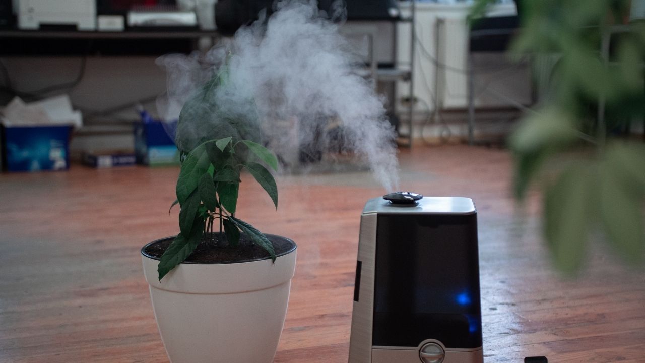
Kondisi udara pada ruangan terkadang cukup kotor dikarenakan banyaknya aktivitas diruangan tersebut, untuk mengatasi hal itu pembersih udara perlu dilakukan secara berkala. Kali ini kita akan mencoba membuat alat pembersih udara iot dalam ruangan yang dapat diopersikan melalui smartphone.
1. Alat / Bahan
- Arduino IDE Download
- Library: Blynk Download
- Library: ESP8266 Download
- NodeMCU 1 Buah
- Sensor MQ-2 1 Buah
- Relay 1 channel 1 Buah
- Motor DC 1 Buah
- Adapter 5V DC 1 Buah
- Project Board 1 Buah
- Kabel Jumper Secukupnya
- Smartphone 1 Buah
Untuk mendapatkan komponen elektronik di atas silahkan temukan.
2. Skema Rangkaian

Gambar Rangkaian Pembersih Udara dalam Ruangan berbasis IoT
Keterangan:
- VU – VCC MQ-2, VCC Relay
- GND – GND MQ-2, GND Relay
- A0 – Pin Data MQ-2
- D4 – Pin Data Relay
- (+) 5V DC – Com Relay
- (-) 5V DC – Kabel Motor DC 1
- NO Relay – Kabel Motor DC 2
3. Layout Blynk

Keterangan:
- Kalibrasi (LED)
- Input V1
- Kipas (LED)
- Input V2
- Konsentrasi Asap (Gauge)
- Input V0, Low = 0, High = 1000
- Label = /pin.#/ppm
- Design Text = Red
- Kipas (Button)
- Input V3, Low = 0, High = 1
- Mode = Switch
4. Langkah Kerja
- Pertama Siapkan alat dan bahan yang akan digunakan
- Kedua Lakukan proses wiring dengan menggunakan Gambar skematik rangkaian diatas
- Ketiga Buka software Arduino IDE yang telah terinstal pada laptop/komputer
- Kemudian unduh semua library di atas dan masukkan libray tersebut dengan cara buka Arduino IDE Selanjutnya pilih Sketch->Include Library->Add.Zip Library
- Lalu ketikkan sketch program pada halaman Arduino IDE
- Kemudian sesuaikan Auth Tokens dengan proyek aplikasi Blynk. Selanjutnya untuk cara setting dan mendapatkan Auth Tokens dapat dilihat pada tutorial berikut:
Setting Blynk untuk NodeMCU ESP8266 - Kemudian ganti ssid dan pass dengan nama wifi dan password wifi yang kalian gunakan
- Selanjutnya Lakukan proses uploading program
- Setelah itu buka aplikasi Blynk
- Kemudian buat layout Blynk seperti gambar di atas.
- Tekan tombol Play pada aplikasi Blynk lalu tunggu hingga proyek kalian terhubung dengan aplikasi Blynk
5. Sketch Program
Dapatkan puluhan ebook gratis dengan registrasi melalui tombol di bawah!
/* Program Pembersih Udara dalam Ruangan berbasis IoT dibuat oleh Indobot */

#include <ESP8266WiFi.h>              //Library ESP8266
#include <BlynkSimpleEsp8266.h>       //Library Blynk

char auth[] = "HoP9z23_PbWp-iEyMBYFGnnALYBvvcXS"; //Token
char ssid[] = "Wifi.id";                          //Nama wifi
char pass[] = "alam oye";                         //Password wifi

BlynkTimer timer;

WidgetLED ledkalibrasi (V1);          //Deklarasi led indikator blynk pada pin V1
WidgetLED ledkipas (V2);

#define kipas 2                       //Kipas pada pin D4

BLYNK_WRITE(V3){                      //Baca pin V3
  int tombolkipas = param.asInt();
  if (tombolkipas == 0){
    digitalWrite(kipas, HIGH);
    Blynk.setProperty(V2, "color", "#ff0000");      //Warna merah
    ledkipas.on();
  }
  else{
    digitalWrite(kipas, LOW);
    Blynk.setProperty(V2, "color", "#15ff00");      //Warna hijau
    ledkipas.on();
  }
}

/************************Hardware Related Macros************************************/
const int MQ_PIN=A0;                                //define which analog input channel you are going to use
int RL_VALUE=5;                                     //define the load resistance on the board, in kilo ohms
float RO_CLEAN_AIR_FACTOR=9.83;                     //RO_CLEAR_AIR_FACTOR=(Sensor resistance in clean air)/RO,
                                                    //which is derived from the chart in datasheet

/***********************Software Related Macros************************************/
int CALIBARAION_SAMPLE_TIMES=50;                    //define how many samples you are going to take in the calibration phase
int CALIBRATION_SAMPLE_INTERVAL=500;                //define the time interal(in milisecond) between each samples in the
                                                    //cablibration phase
int READ_SAMPLE_INTERVAL=50;                        //define how many samples you are going to take in normal operation
int READ_SAMPLE_TIMES=5;                            //define the time interal(in milisecond) between each samples in
                                                    //normal operation

/**********************Application Related Macros**********************************/
#define         GAS_LPG             0
#define         GAS_CO              1
#define         GAS_SMOKE           2

/*****************************Globals***********************************************/
float           LPGCurve[3]  =  {2.3,0.21,-0.47};   //two points are taken from the curve.
                                                    //with these two points, a line is formed which is "approximately equivalent"
                                                    //to the original curve.
                                                    //data format:{ x, y, slope}; point1: (lg200, 0.21), point2: (lg10000, -0.59)
float           COCurve[3]  =  {2.3,0.72,-0.34};    //two points are taken from the curve.
                                                    //with these two points, a line is formed which is "approximately equivalent"
                                                    //to the original curve.
                                                    //data format:{ x, y, slope}; point1: (lg200, 0.72), point2: (lg10000,  0.15)
float           SmokeCurve[3] ={2.3,0.53,-0.44};    //two points are taken from the curve.
                                                    //with these two points, a line is formed which is "approximately equivalent"
                                                    //to the original curve.
                                                    //data format:{ x, y, slope}; point1: (lg200, 0.53), point2: (lg10000,  -0.22)
float           Ro           =  10;                 //Ro is initialized to 10 kilo ohms

//Pilih jenis gas yang akan dideteksi dengan menghilangkan komentar "//"

//long iPPM_LPG = 0;
//long iPPM_CO = 0;
long iPPM_Smoke = 0;

void setup() {
  Blynk.begin(auth, ssid, pass);          //Inisialisasi token, wifi dan password
  timer.setInterval(1000L, sendSensor);   //Kirim data sensor

  pinMode(kipas, OUTPUT);                 //Setting I/O
  digitalWrite(kipas, HIGH);              //Set kondisi awal

  Blynk.setProperty(V1, "color", "#ff0000");          //Warna merah
  ledkalibrasi.on();

  Ro = MQCalibration(MQ_PIN);                         //Calibrating the sensor. Please make sure the sensor is in clean air
}

void loop() {
  Blynk.run();                                        //Jalankan pembacaan Blynk
  timer.run();

  Blynk.setProperty(V1, "color", "#15ff00");          //Warna hijau
  ledkalibrasi.on();
  //iPPM_LPG = MQGetGasPercentage(MQRead(MQ_PIN)/Ro,GAS_LPG);
  //iPPM_CO = MQGetGasPercentage(MQRead(MQ_PIN)/Ro,GAS_CO);
  iPPM_Smoke = MQGetGasPercentage(MQRead(MQ_PIN)/Ro,GAS_SMOKE);
}

float MQResistanceCalculation(int raw_adc)
{
  return ( ((float)RL_VALUE*(1023-raw_adc)/raw_adc));
}

float MQCalibration(int mq_pin)
{
  int i;
  float val=0;

  for (i=0;i<CALIBARAION_SAMPLE_TIMES;i++) {            //take multiple samples
    val += MQResistanceCalculation(analogRead(mq_pin));
    delay(CALIBRATION_SAMPLE_INTERVAL);
  }
  val = val/CALIBARAION_SAMPLE_TIMES;                   //calculate the average value
  val = val/RO_CLEAN_AIR_FACTOR;                        //divided by RO_CLEAN_AIR_FACTOR yields the Ro
  return val;                                                      //according to the chart in the datasheet

}

float MQRead(int mq_pin)
{
  int i;
  float rs=0;

  for (i=0;i<READ_SAMPLE_TIMES;i++) {
    rs += MQResistanceCalculation(analogRead(mq_pin));
    delay(READ_SAMPLE_INTERVAL);
  }

  rs = rs/READ_SAMPLE_TIMES;

  return rs;
}

long MQGetGasPercentage(float rs_ro_ratio, int gas_id)
{
  if ( gas_id == GAS_LPG ) {
     return MQGetPercentage(rs_ro_ratio,LPGCurve);
  } else if ( gas_id == GAS_CO ) {
     return MQGetPercentage(rs_ro_ratio,COCurve);
  } else if ( gas_id == GAS_SMOKE ) {
     return MQGetPercentage(rs_ro_ratio,SmokeCurve);
  }

  return 0;
}

long  MQGetPercentage(float rs_ro_ratio, float *pcurve)
{
  return (pow(10,( ((log(rs_ro_ratio)-pcurve[1])/pcurve[2]) + pcurve[0])));
}

void sendSensor(){                  //Kirim data sensor
  Blynk.virtualWrite(V0, iPPM_Smoke);  //Asap ke pin V0
}
Kesimpulan:
Hasil proyek ini ketika konsentrasi asap dalam ruangan terdeteksi tinggi/sangat tinggi kita dapat membersihkan udara dengan menekan button kipas, maka kipas akan mulai berputar dan mulai membersihkan serta menganti udara diruangan tersebut.
Mau belajar elektronika dasar? Arduino? atau Internet of Things? Ikuti kursus online Indobot Academy!


Warning: Undefined variable $req in /www/wwwroot/blog.indobot.co.id/wp-content/themes/generatepress/functions.php on line 162
Warning: Undefined variable $commenter in /www/wwwroot/blog.indobot.co.id/wp-content/themes/generatepress/functions.php on line 163
Warning: Trying to access array offset on value of type null in /www/wwwroot/blog.indobot.co.id/wp-content/themes/generatepress/functions.php on line 163
Warning: Undefined variable $aria_req in /www/wwwroot/blog.indobot.co.id/wp-content/themes/generatepress/functions.php on line 163
Warning: Undefined variable $req in /www/wwwroot/blog.indobot.co.id/wp-content/themes/generatepress/functions.php on line 167
Warning: Undefined variable $commenter in /www/wwwroot/blog.indobot.co.id/wp-content/themes/generatepress/functions.php on line 168
Warning: Trying to access array offset on value of type null in /www/wwwroot/blog.indobot.co.id/wp-content/themes/generatepress/functions.php on line 168
Warning: Undefined variable $aria_req in /www/wwwroot/blog.indobot.co.id/wp-content/themes/generatepress/functions.php on line 169